SHAFT & BEARING VIBRATION MONITORING

Description
Ensuring the health and performance of rotating machinery is crucial for operational efficiency. The amplitude of radial vibrations and the radial position of the shaft are critical indicators of the mechanical condition of rotating machinery. Monitoring these parameters allows for early detection of common malfunctions such as rotor unbalance, misalignment, and bearing wear, which are crucial for maintaining operational integrity and efficiency. This proactive approach helps reduce maintenance costs and improve safety.
Key assets such as hydro turbines, gas turbines, steam turbines, pumps, fans, and cooling towers require advanced protection and monitoring systems to detect vibrations that conventional shaft measurement techniques might miss. According to ISO standards and API guidelines, it is recommended to use relative sensors (Proximity Probes) whenever there are plain bearings. These standards also recommend the use of absolute sensors (PAS/PVS or LVS). These documents recommend vibration levels by type of machine/power/speed in both relative terms (µm PkPk) and absolute terms (mm/s RMS). Both types of measurements are commonly installed on machines.
- Proximity Probes: Used for relative vibration monitoring to measure the displacement of the shaft.
- PAS/PVS: These are piezoelectric sensors based on the seismic mass principle.
- LVS: This is an electrodynamic sensor using an electromagnetic principle.
Adhering to ISO-20816 standards, our shaft and bearing vibration monitoring systems provide comprehensive insights into machine health, enhancing preventive maintenance strategies and reducing unplanned downtime.
Typical faults detections
- Unbalance: Identified through consistent and periodic vibration patterns, indicating a mass imbalance in the rotating components.
- Misalignment: Detected by uneven vibration signatures across machine components, often leading to premature wear.
- Wear of roller bearings: Identified through abnormal vibration patterns, indicating reduced bearing life.
- Damages or wear of plain bearings: Evidenced by increased friction and vibration levels, pointing to the need for immediate inspection.
- Looseness: Indicated by a sudden increase in vibration amplitude, often caused by loose components or fixtures within the machinery.
- Faults on motors/generators: Detected by variations in vibration patterns specific to electrical faults, such as rotor bar issues, eccentricity, or winding problems.
Typical installation
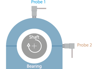
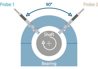
Our standard installation includes two proximity probes and two absolute vibration sensors. For machines with a horizontal axis, the proximity probes are often positioned at -45° and +45° relative to the vertical. The absolute sensors, also two, can be placed on the same axes as the proximity probes (-45° / +45°) or on orthogonal axes (vertical and horizontal, but also 90° between each other). This setup ensures comprehensive coverage and accurate detection of vibration anomalies.


Choosing Between Piezoelectric Accelerometers and Electrodynamic Sensors for Absolute Vibration Monitoring
Our system utilizes either two piezoelectric accelerometers or electrodynamic sensors for comprehensive absolute vibration monitoring. The choice between these two types of sensors depends on several factors, including the frequency range of interest, environmental conditions, and the specific characteristics of the machinery being monitored.
Piezoelectric Accelerometers (PAS/PVS)
- Frequency Range: Highly effective for measuring a wide range of frequencies, suitable for moderate to high-speed machinery where high-frequency vibrations are common.
- Sensitivity: thanks to its native good sensitivity at high frequencies, it can detect small changes in vibration amplitudes, crucial for early detection of potential issues.
- Application: Best suited for a variety of industrial applications such as pumps, motors, fans, and other Balance of Plant (BoP) equipment where rapid response and accuracy are needed.
Electrodynamic Sensors (LVS)
- Frequency Range: Optimized for lower frequency vibrations, typical in heavy industrial machinery and structures operating at slower speeds.
- Durability and Stability: More robust and better suited for harsh industrial environments with high levels of mechanical noise.
- Application: Ideal for monitoring heavy-duty turbines, and large rotating machinery where vibrations occur at lower frequencies.
Monitoring parameters
Relative Shaft Vibration
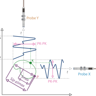
- Smax (μm PkPk): Measures the maximum peak-to-peak vibration of the shaft over a given time period (typically 1 second), indicating the total range of movement which helps in identifying excessive vibrations.
- Shaft Position (μm mean): Records the average position of the shaft over time, providing insights into the central tendency of the shaft’s movement which can indicate misalignment.
- Harmonic and Phase: Analyzes the frequency components and their phase relationships, aiding in identifying specific vibration sources such as unbalance or mechanical looseness.
Absolute Bearing Vibration
- TRMS (mm/s RMS): True Root Mean Square of velocity, this parameter measures the overall vibration velocity, which is used to assess the overall condition of the bearing.
- Harmonic and Phase: Similar to shaft vibration, this analyzes the frequency components and phase angles to diagnose issues like bearing defects or misalignment.
Maximizing Machine Performance with CMS-500P Condition Monitoring Software
The CMS-500P Orca, our advanced condition monitoring software, is specifically designed to integrate seamlessly with our vibration monitoring systems. This software is a pivotal tool in predictive maintenance, providing real-time analytics and deep insights into the health of rotating machinery. By utilizing the CMS-500P Orca, operators can visualize complex data through an intuitive interface, which displays key metrics such as vibration levels, trends, and operational anomalies.
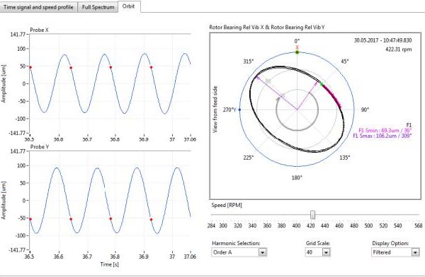
Example of Orbit Visualization with the CMS-500P
Shaft Orbit Visualization: Using two orthogonal relative sensors (proximity probes), we can trace the shaft's orbit. From the orbit, Smax parameters can be derived.


LET'S KEEP IN TOUCH
Sign up to receive our newsletters


